
The on grid inverter circuit diagram typically consists of several key components, including the solar panels, DC isolator, MPPT charge controller, inverter, grid connection, and electrical protection devices.
This application note presents the fundamental RF parametric measurements necessary to characterize GSM900, DCS1800 and PCS1900 base transceiver stations and their components.
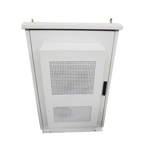
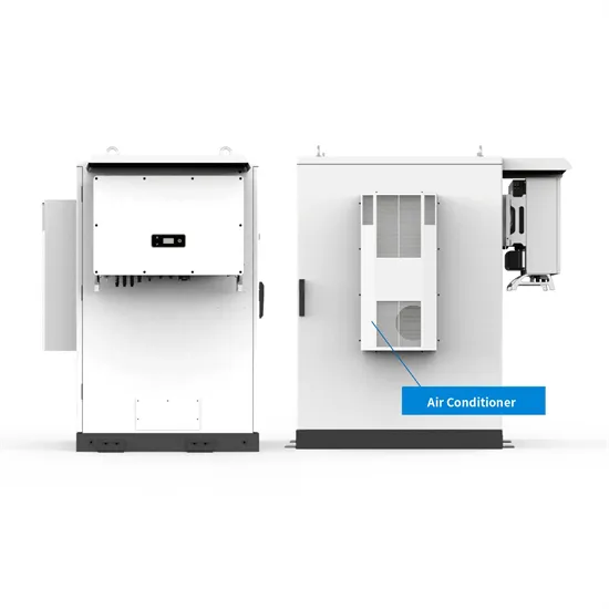
Solution: Refer to the product manual for installation spacing, the bottom of the conventional installation inverter is≥500mm from the ground; For tilt-mounted installations, the distance from the inverter AC-DC waterproof joint to the roof should be ≥300mm to prevent water.
Under grid voltage sags, over current protection and exploiting the maximum capacity of the inverter are the two main goals of grid-connected PV inverters.
The article discusses the costs associated with building and maintaining a communication base station, categorizing them into initial setup costs such as site acquisition, design and engineering, equipment procurement, construction and installation, permits and.
The protection of GSM and base station towers from lightning and overvoltage is provided by integrating external lightning systems, internal lightning systems, earthing, equipotential bonding and LV surge arrester protection techniques within the framework of IEC-62305.
This guide will walk you through the process of connecting an on-grid solar inverter, ensuring a smooth and efficient setup for your solar power system. Please install where children can not touch.
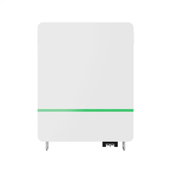
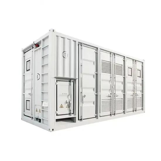
E-START ENERGY delivers utility-scale BESS for frequency regulation, peak shaving, electricity market participation, and grid-side solutions. Request a free consultation and get a custom quote for your project — from 1MW to 500MW+.
Have questions about grid-scale energy storage, frequency regulation systems, peak shaving solutions, or grid interconnection technology? Reach out – our energy storage experts are ready to assist.