
A conceptual power train schematic diagram below illustrates the principles of operation of a three-stage grid tie inverter. Such a topology can be useful for low-voltage inputs (such as 12V) in grounded systems. The control circuits and miscellaneous details are not shown.
Open-circuit voltage, or Voc, is the maximum voltage a solar panel can produce when not connected to an electrical circuit. It's like a river at its highest point, ready to cascade down when released. With no electrical load, there's no current, and the voltage soars to its.
A free online tool to easily create, customize, and export professional solar power system diagrams. Drag and drop components, connect lines, and save your work.
The working principle of the inverter is to use the power from a DC Source such as the solar panel and convert it into AC power. This conversion process can be done with the help of a set of IGBTs (Insulated Gate Bipolar.
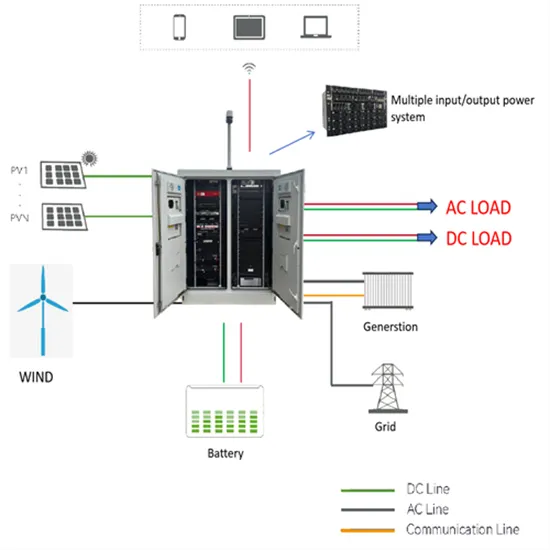
When you switch on the first things you will notice on a solar inverter screen battery voltage and output voltage positioned at the top. Below it,The entire system diagram is shown with flowing arrows, which indicates the current operational condition of each solar system.
This is caused by low intermediate circuit DC voltage. This can be caused by a missing supply voltage phase from a blown fuse or faulty isolator or contactor or internal rectifier bridge fault or simply low mains voltage. POSSIBLE FIXES: Check mains supply and fuses.
The wiring diagram will indicate where these fuses or circuit breakers need to be located in the combiner box. Additionally, the diagram will show the wiring connections for the positive and negative terminals of each string of solar panels and the wires.
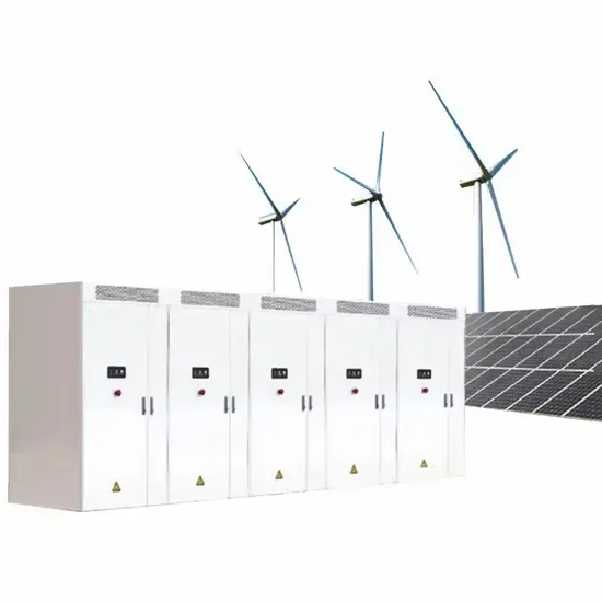
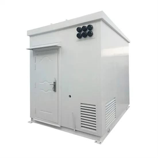
E-START ENERGY delivers utility-scale BESS for frequency regulation, peak shaving, electricity market participation, and grid-side solutions. Request a free consultation and get a custom quote for your project — from 1MW to 500MW+.
Have questions about grid-scale energy storage, frequency regulation systems, peak shaving solutions, or grid interconnection technology? Reach out – our energy storage experts are ready to assist.